
Page 208 - Build Your Own Transistor Radios a Hobbyists Guide to High-Performance and Low-Powered Radio Circuits
P. 208
Input Signal Level VD gm @ l-mA IeQ G m @ l-mA lea Gn/9 for Any IeQ
m
0.001 is small signal 0.038 mho 0.038 mho 1.0
0.013 is large signal 0.037 mho 0.97
0.026 is large signal 0.034 mho 0.893
0.052 is large signal 0.026 mho 0.698
0.104 is large signal 0.016 mho 0.432
0.156 is large signal 0.012 mho 0.304
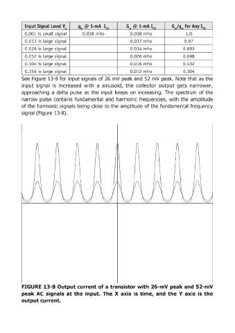
See Figure 13-8 for input signals of 26 mV peak and 52 mV peak. Note that as the
input signal is increased with a sinusoid, the collector output gets narrower,
approaching a delta pulse as the input keeps on increasing. The spectrum, of the
narrow pulse contains fundamental and harmonic frequencies, with the amplitude
of the harmonic signals being close to the amplitude of the fundamental frequency
signa:1 (Figure 13-8).
FIGURE 13-8 Output current of a transistor with 26-mV peak and 52-mV
peak ACsignals at the input. The X axis is time, and the Y axis is the
output cu rrent.