
Page 206 - Build Your Own Transistor Radios a Hobbyists Guide to High-Performance and Low-Powered Radio Circuits
P. 206
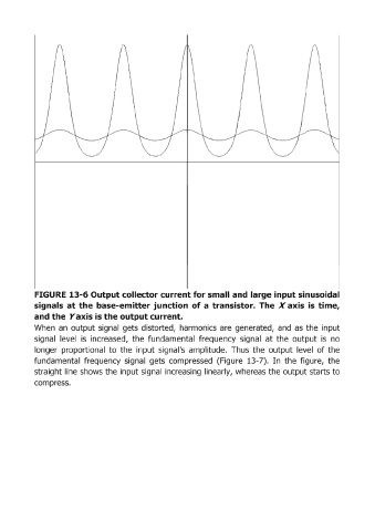
FIGURE  13-6 Output collector current for small and large input sinusoidal
            signals  at the base-emitter junction  of a  transist.or.  The  X  axis  is  time,
            and the  Yaxis is the output current.
            When  an  output signal  gets  distorted,  harmonics  are  generated,  and  as  the  input

            signal  level  is  increased,  the  fundamental  frequency  signal  at  the  output  is  no
            longer  proportional  to  the  input  signal's  amplitude.  Thus  the  output  level  of the
            fundamental  frequency  signal  gets  compressed  (Figure  13-7).  In  the  figure,  the
            straight Iline shows the input signal  increasing  linearly,  whereas the output starts to
            compress.