
Page 207 - Build Your Own Transistor Radios a Hobbyists Guide to High-Performance and Low-Powered Radio Circuits
P. 207
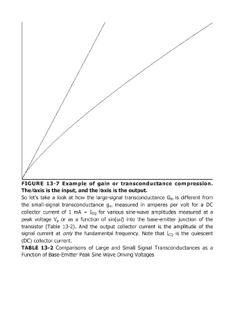
FIGURE  13-7  Example  of gain  or transconductance  com ,pression.
            Thexaxisis the input, and the >axis is the output.
            So  let's take  a look at how the  large-signal  transconductance  Gm  is  different from
            the  small-signal  transconductance  gm  measured  in  amperes  per  volt  for  a  DC
            collector  current  of  1  mA  = ICQ  for  various  sine-wave  a1mplitudes  measured  at  a

            peak  voltage  Vp  or  as  a  function  of sin(w"  into  the  base-emitter junction  of the
            transistor  (Table  13-2).  And  the  output  collector  current  is  the  amplitude  of the
            signal  current  at  only the  fundamental  frequency.  Note  that  ICQ  is  the  quiescent

            (DC) collector current.
            TABLE  13-2 Comparisons  of Large  and  Small  Signal  Transconductances  as  a
            Function of Base-Emitter Peak Sine Wave Driving Voltages