
Page 210 - Build Your Own Transistor Radios a Hobbyists Guide to High-Performance and Low-Powered Radio Circuits
P. 210
by about two-fold. For example, with a DC collector current of 1 mA = I cQ , the
input resistance of a common base amplifier is 26
for small signals such as a 1 mV peak sine wave AC signal across the emitter-base
junction. If the input signal is increased to a 104 mV peak sine wave, the input
resistance is increased from 26
to 60
pertaining to the fundamental frequency of the sine wave. In another example, if
the ICQ = 0.1 mA, the small signal input resistance into the common base amplifier
is 260
, and the large-signal input resistance with a 104 mV peak sine wave is 600
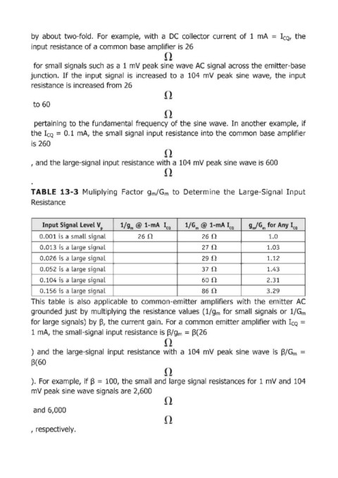
TABLE 13-3 Muliplying Factor gm/Gm to Determine the Large-Signal Input
Resistance
Input Signal Level V l/g m @ I-mA Ica l/G m @ I-mA Ica gm/Gm for Any lea
p
0.001 is a small signal 26 n 260 1.0
0.013 ;s a large signaL 270 1.03
0.026 is a Large signal 290 1.12
0.052 is a large signaL 370 1.43
0.104 is a large signaL 600 2.31
0.156 is a Large signaL 86 n 3.29
This table is also applicable to common-emitter amplifiers with the emitter AC
grounded just by multiplying the resistance values (l/g m for small signals or l/G m
for large signals) by ~, the current gain. For a common emitter amplifier with ICQ =
1 mA, the small-signal input resistance is ~/gm = 13(26
) and the large-signal input resistance with a 104 mV peak sine wave is I3/G m =
~(60
). For example, if f3 = lOO, the small and large signal resistances for 1 mV and 104
mV peak sine wave signals are 2,600
and 6,000
, respectively.