
Page 205 - Build Your Own Transistor Radios a Hobbyists Guide to High-Performance and Low-Powered Radio Circuits
P. 205
(KT Iq) = v,- = 0.026 volt direct current (DC) at room temperature. V is also known
T
as the thermal voltage.
The small signal transconductance of the bipolar transistor at a particular DC
collector current ICQ is given by
mall i 11 1 = _ "_, = I 'Q --- 13-2)
"' = ________ -
I ' f\
''I' 0.026 V m
--er-
If we did not know about Equation (13-2), there is another way to indirectly come
up with the transistor's transconductance by plugging values into Equation (13-1).
For Table 13-1, Is = 0.01 pA. Note that the transconductance is independent of the
value of Is.
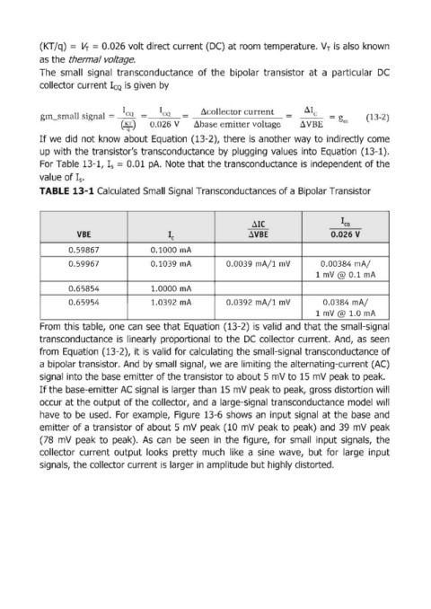
TABLE 13-1 Calculated Small Signal Transconductances of a Bipolar Transistor
~IC lea
--
VBE le ~VBE 0.026 V
0.59867 0.1000 mA
0.59967 0.1039 mA 0.0039 mAil mV 0.00384 mAl
1 mV @ 0.1 mA
0.65854 1.0000 mA
0.65954 1.0392 mA 0.0392 mAil mV 0.0384 mAl
1 mV@ 1.0 mA
From this table, one can see that Equation (13-2) is valid and that the small-signal
transconductance is linearly proportional to the DC coUector current. And, as seen
from Equation (13-2), it is valid for calculating the small-signal transconductance of
a bipolar transistor. And by small signal, we are limiting the alternating-current (AC)
signa~1 into the base emitter of the transistor to about 5 mV to 15 mV peak to peak.
If the base-emitter AC signal is larger than 15 mV peak to peak, gross distortion will
occur at the output of the collector, and a large-signal transconductance model will
have to be used. For example, Figure 13-6 shows an input signal at the base and
emitter of a transistor of about 5 mV peak (10 mV peak to peak) and 39 mV peak
(78 mV peak to peak). As can be seen in the figure, for small input signals, the
collector current output looks pretty much like a sine wave, but for large input
signa: ls, the collector current is larger in amplitude but highly distorted.