
Page 201 - Build Your Own Transistor Radios a Hobbyists Guide to High-Performance and Low-Powered Radio Circuits
P. 201
Filter
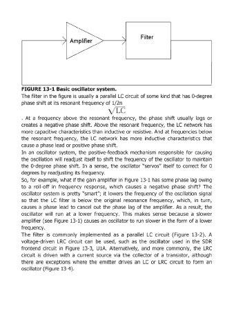
FIGURE 13-1 Basic oscillator system.
The filter in the figure is usually a parallel Le circuit of some kind that has a-degree
phase shift at its resonant frequency of 1/2n
. At a frequency above the resonant frequency, the phase shift usually lags or
creates a negative phase shift. Above the resonant frequency, the Le network has
more capacitive characteristics than inductive or resistive. And at frequencies below
the resonant frequency, the Le network has more inductive characteristics that
cause a phase lead or positive phase shift.
In an oscillator system, the positive-feedback mechanism responsible for causing
the oscillation will readjust itself to shift the frequency of the oscillator to maintain
the a-degree phase shift. In a sense, the oscillator "servos" itself to correct for a
degrees by readjusting its frequency.
So, for example, what if the gain amplifier in Figure 13-1 has some phase lag owing
to a roll-off in frequency response, which causes a negative phase shift? The
oscillator system is pretty "smart"; it lowers the frequency of the oscillation signal
so that the LC filter is below the original resonance frequency, which, in turn,
causes a phase lead to cancel out the phase lag of the amplifier. As a result, the
oscillator will run at a lower frequency. This makes sense because a slower
amplifier (see Figure 13-1) causes an oscillator to run slower in the form of a lower
frequency.
The filter is commonly implemented as a parallel Le circuit (Figure 13-2). A
voltage-driven LRC circuit can be used, such as the oscillator used in the SDR
frontend circuit in Figure 13-3, U1A. Alternatively, and more commonly, the LRC
circuit is driven with a current source via the collector of a transistor, although
there are exceptions where the emitter drives an Le or LRC circuit to form an
oscillator (Figure 13-4).