
Page 204 - Build Your Own Transistor Radios a Hobbyists Guide to High-Performance and Low-Powered Radio Circuits
P. 204
Transconductance Devi ce
+ Vout
v Rin
R 1 L1 C1
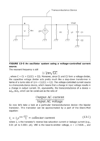
FIGURE 13-5 An oscillator system using a voltage-controlled current
source.
The resonant frequency is still
/
, where C = Cl x C2/(C1 + C2). Moreover, since Cl and C2 form a voltage divider,
the capacitive voltage divider acts pretty much like a step-down transformer in
terms of a turns ratio of 1/ n = C1/(C1 + C2). The voltage-controlled current source
is a transconductance device, which means that a change in input voltage results in
a change in output current. Or, equivalently, the transconduetance of a device =
8.fout 18. Vln, which can be construed as the ratio of
So now let's take a look at a particular transconductance device-the bipolar
transistor. This transistor can be approximated by a part of the Ebers-MolI
equation:
n 1 -
where Is is the transistor's reverse bias saturation current or leakage current (e.g.,
0 .. 01 pA to 0.0001 pA), VBE is the base-ta-emitter voltage, e = 2.71828. '" and