
Page 74 - Build a Remote Controlled Robot
P. 74
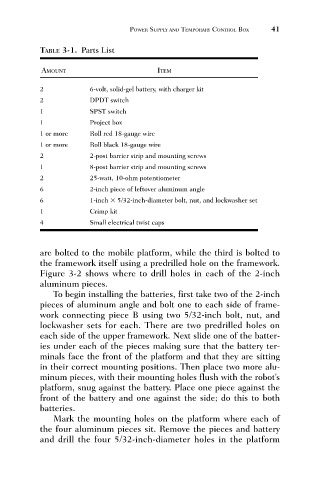
TABLE 3-1. Parts List
                                                              ITEM
                              AMOUNT                  POWER SUPPLY AND TEMPORARY CONTROL BOX  41
                              2            6-volt, solid-gel battery, with charger kit
                              2            DPDT switch
                              1            SPST switch
                              1            Project box
                              1 or more    Roll red 18-gauge wire
                              1 or more    Roll black 18-gauge wire
                              2            2-post barrier strip and mounting screws
                              1            8-post barrier strip and mounting screws
                              2            25-watt, 10-ohm potentiometer
                              6            2-inch piece of leftover aluminum angle
                              6            1-inch   5/32-inch-diameter bolt, nut, and lockwasher set
                              1            Crimp kit
                              4            Small electrical twist caps


                              are bolted to the mobile platform, while the third is bolted to
                              the framework itself using a predrilled hole on the framework.
                              Figure 3-2 shows where to drill holes in each of the 2-inch
                              aluminum pieces.
                                 To begin installing the batteries, first take two of the 2-inch
                              pieces of aluminum angle and bolt one to each side of frame-
                              work connecting piece B using two 5/32-inch bolt, nut, and
                              lockwasher sets for each. There are two predrilled holes on
                              each side of the upper framework. Next slide one of the batter-
                              ies under each of the pieces making sure that the battery ter-
                              minals face the front of the platform and that they are sitting
                              in their correct mounting positions. Then place two more alu-
                              minum pieces, with their mounting holes flush with the robot’s
                              platform, snug against the battery. Place one piece against the
                              front of the battery and one against the side; do this to both
                              batteries.
                                 Mark the mounting holes on the platform where each of
                              the four aluminum pieces sit. Remove the pieces and battery
                              and drill the four 5/32-inch-diameter holes in the platform