
Page 76 - Build a Remote Controlled Robot
P. 76
POWER SUPPLY AND TEMPORARY CONTROL BOX
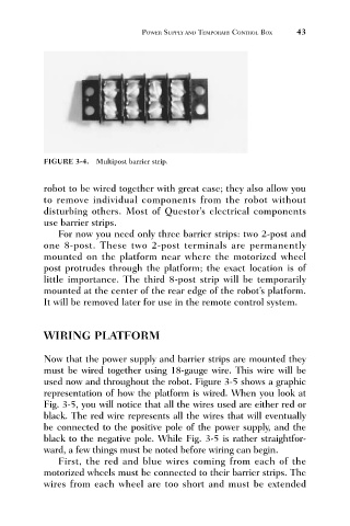
FIGURE 3-4. Multipost barrier strip. 43
robot to be wired together with great ease; they also allow you
to remove individual components from the robot without
disturbing others. Most of Questor’s electrical components
use barrier strips.
For now you need only three barrier strips: two 2-post and
one 8-post. These two 2-post terminals are permanently
mounted on the platform near where the motorized wheel
post protrudes through the platform; the exact location is of
little importance. The third 8-post strip will be temporarily
mounted at the center of the rear edge of the robot’s platform.
It will be removed later for use in the remote control system.
WIRING PLATFORM
Now that the power supply and barrier strips are mounted they
must be wired together using 18-gauge wire. This wire will be
used now and throughout the robot. Figure 3-5 shows a graphic
representation of how the platform is wired. When you look at
Fig. 3-5, you will notice that all the wires used are either red or
black. The red wire represents all the wires that will eventually
be connected to the positive pole of the power supply, and the
black to the negative pole. While Fig. 3-5 is rather straightfor-
ward, a few things must be noted before wiring can begin.
First, the red and blue wires coming from each of the
motorized wheels must be connected to their barrier strips. The
wires from each wheel are too short and must be extended