
Page 81 - Build a Remote Controlled Robot
P. 81
48
CHAPTER THREE
forward, reverse, or not at all. How this system is used to control
Questor will be described later in the chapter.
CONTROL BOX CONSTRUCTION
The temporary control box will house all of Questor’s control
electronics in this stage of his construction. The box itself
should be approximately 4 4 inches square to allow room for
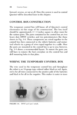
the various parts. The parts contained in the control box are two
heavy duty DPDT switches and two potentiometers like those
shown in Fig. 3-8. These components are wired together in the
control box then connected to the robot’s batteries and motor-
ized wheels via a group of wires taped together in a cable. How
the parts are mounted in the control box is up to you; however,
Fig. 3-9 shows a recommended layout. To mount the parts you
will have to remove the box’s overplate on the control box and
drill mounting holes in that plate.
WIRING THE TEMPORARY CONTROL BOX
The wire used in the temporary control box and throughout
the robot is an 18-gauge-type colored either black or red. Again,
red is for all wires connected to the positive pole of the batteries
and black is for all to the negative. This makes it easier to trace
FIGURE 3-8. DPDT and “pots” switch.