
Page 82 - Build a Remote Controlled Robot
P. 82
POWER SUPPLY AND TEMPORARY CONTROL BOX
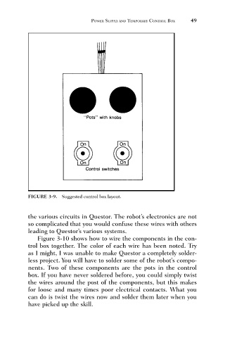
FIGURE 3-9. Suggested control box layout. 49
the various circuits in Questor. The robot’s electronics are not
so complicated that you would confuse these wires with others
leading to Questor’s various systems.
Figure 3-10 shows how to wire the components in the con-
trol box together. The color of each wire has been noted. Try
as I might, I was unable to make Questor a completely solder-
less project. You will have to solder some of the robot’s compo-
nents. Two of these components are the pots in the control
box. If you have never soldered before, you could simply twist
the wires around the post of the components, but this makes
for loose and many times poor electrical contacts. What you
can do is twist the wires now and solder them later when you
have picked up the skill.