
Page 80 - Build a Remote Controlled Robot
P. 80
POWER SUPPLY AND TEMPORARY CONTROL BOX
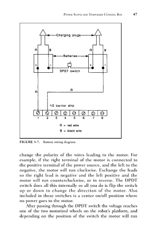
FIGURE 3-7. Battery wiring diagram. 47
change the polarity of the wires leading to the motor. For
example, if the right terminal of the motor is connected to
the positive terminal of the power source, and the left to the
negative, the motor will run clockwise. Exchange the leads
so the right lead is negative and the left positive and the
motor will run counterclockwise, or in reverse. The DPDT
switch does all this internally so all you do is flip the switch
up or down to change the direction of the motor. Also
included in these switches is a center on/off position where
no power goes to the motor.
After passing through the DPDT switch the voltage reaches
one of the two motorized wheels on the robot’s platform, and
depending on the position of the switch the motor will run