
Page 101 - Building A Succesful Board-Test Strategy
P. 101
Test Methods 8?
Bad Bad
1 r
Bus Problem LooponFailure
ROM Problem
ROM-Decoder Identifywith bench instruments
Failure
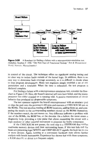
Figure 2-29 A flowchart for finding a failure with a microprocessor-emulation test.
(Scheiber, Stephen F. 1990. "The New Face of Functional Testing," Test & Measurement
World, Newton, Massachusetts.)
in control of the circuit. The technique offers no significant analog testing and
no clear way to isolate faults outside of the kernel logic. In addition, there is no
easy way to determine fault coverage accurately, so it is difficult to decide when
to stop program development. Many test engineers simply establish a set of test
parameters and a timetable. When the time is exhausted, the test program is
declared complete.
For finding a failure with a microprocessor-emulation test, consider the flow-
chart in Figure 2-29. Here, the board's internal self-tests have failed, and the micro-
processor has either stopped or is running wild. A passive examination of circuit
behavior has produced no diagnosable symptoms.
The test operator replaces the board's microprocessor with an emulator pod
or clips the pod onto the processor's I/O pins and executes a CHECKSUM test on
the ROMs. This test involves reading all ROM locations, adding them up, and com-
paring the results to the corresponding numbers stored on the ROMs themselves.
If the numbers match, the test moves on. Any difference indicates a problem with
one of the ROMs, the ROM bus, or the decoder. On a failure, the tester enters a
diagnostic loop, providing a sync pulse that allows examining the circuit with a
logic analyzer or other external instrument to pinpoint the faulty component.
If the CHECKSUM test passes, the next step is a TESTRAM that verifies
read/write memory devices and their surrounding buses. If this test fails and the
buses are presenting legal WRITE and CHIP-SELECT signals, the fault lies in one
or more devices. Again, looping at a convenient hardware state allows further
analysis with bench instruments. Experience has shown that with these symptoms,
a RAM decoder or driver is a frequent culprit.