
Page 99 - Building A Succesful Board-Test Strategy
P. 99
Tesf Methods 85
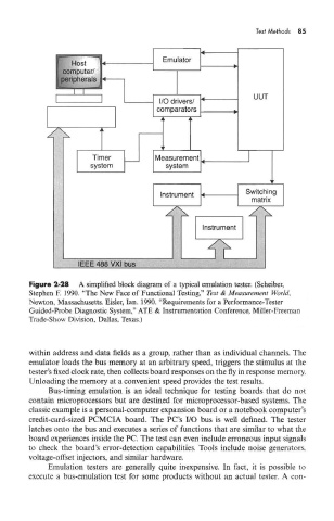
Figure 2-28 A simplified block diagram of a typical emulation tester. (Scheiber,
Stephen F. 1990. "The New Face of Functional Testing," Test & Measurement World,
Newton, Massachusetts. Eisler, Ian. 1990. "Requirements for a Performance-Tester
Guided-Probe Diagnostic System," ATE & Instrumentation Conference, Miller-Freeman
Trade-Show Division, Dallas, Texas.)
within address and data fields as a group, rather than as individual channels. The
emulator loads the bus memory at an arbitrary speed, triggers the stimulus at the
tester's fixed clock rate, then collects board responses on the fly in response memory
Unloading the memory at a convenient speed provides the test results.
Bus-timing emulation is an ideal technique for testing boards that do not
contain microprocessors but are destined for microprocessor-based systems. The
classic example is a personal-computer expansion board or a notebook computer's
credit-card-sized PCMCIA board. The PC's I/O bus is well defined. The tester
latches onto the bus and executes a series of functions that are similar to what the
board experiences inside the PC. The test can even include erroneous input signals
to check the board's error-detection capabilities. Tools include noise generators,
voltage-offset injectors, and similar hardware.
Emulation testers are generally quite inexpensive. In fact, it is possible to
execute a bus-emulation test for some products without an actual tester. A con-