
Page 94 - Building A Succesful Board-Test Strategy
P. 94
80 BUILDING A SUCCESSFUL BOARD-TEST STRATEGY
GND
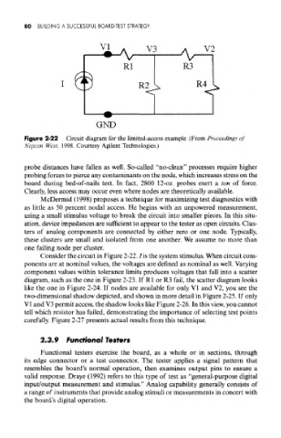
Figure 2-22 Circuit diagram for the limited-access example. (From Proceedings of
Nepcon West, 1998. Courtesy Agilent Technologies.)
probe distances have fallen as well. So-called "no-clean" processes require higher
probing forces to pierce any contaminants on the node, which increases stress on the
board during bed-of-nails test. In fact, 2800 12-oz. probes exert a ton of force.
Clearly, less access may occur even where nodes are theoretically available.
McDermid (1998) proposes a technique for maximizing test diagnostics with
as little as 50 percent nodal access. He begins with an unpowered measurement,
using a small stimulus voltage to break the circuit into smaller pieces. In this situ-
ation, device impedances are sufficient to appear to the tester as open circuits. Clus-
ters of analog components are connected by either zero or one node. Typically,
these clusters are small and isolated from one another. We assume no more than
one failing node per cluster.
Consider the circuit in Figure 2-22. I is the system stimulus. When circuit com-
ponents are at nominal values, the voltages are defined as nominal as well. Varying
component values within tolerance limits produces voltages that fall into a scatter
diagram, such as the one in Figure 2-23. If Rl or R3 fail, the scatter diagram looks
like the one in Figure 2-24. If nodes are available for only VI and V2, you see the
two-dimensional shadow depicted, and shown in more detail in Figure 2-25. If only
V1 and V3 permit access, the shadow looks like Figure 2-26. In this view, you cannot
tell which resistor has failed, demonstrating the importance of selecting test points
carefully. Figure 2-27 presents actual results from this technique.
2.3.9 Functional Testers
Functional testers exercise the board, as a whole or in sections, through
its edge connector or a test connector. The tester applies a signal pattern that
resembles the board's normal operation, then examines output pins to ensure a
valid response. Draye (1992) refers to this type of test as "general-purpose digital
input/output measurement and stimulus." Analog capability generally consists of
a range of instruments that provide analog stimuli or measurements in concert with
the board's digital operation.