
Page 92 - Building A Succesful Board-Test Strategy
P. 92
78 BUILDING A SUCCESSFUL BOARD-TEST STRATEGY
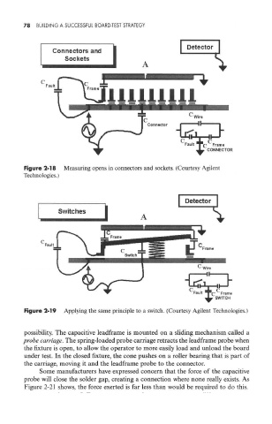
Figure 2-18 Measuring opens in connectors and sockets. (Courtesy Agilent
Technologies.)
Figure 2-19 Applying the same principle to a switch. (Courtesy Agilent Technologies.)
possibility. The capacitive leadframe is mounted on a sliding mechanism called a
probe carriage. The spring-loaded probe carriage retracts the leadframe probe when
the fixture is open, to allow the operator to more easily load and unload the board
under test. In the closed fixture, the cone pushes on a roller bearing that is part of
the carriage, moving it and the leadframe probe to the connector.
Some manufacturers have expressed concern that the force of the capacitive
probe will close the solder gap, creating a connection where none really exists. As
Figure 2-21 shows, the force exerted is far less than would be required to do this.