
Page 91 - Building A Succesful Board-Test Strategy
P. 91
Test Methods 77
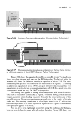
Figure 2-16 Anatomy of an open-solder capacitor, (Courtesy Agilent Technologies.)
Figure 2-17 The measurement system places a conductor over the lead frame, forming
an additional capacitor of about lOOfF. (Courtesy Agilent Technologies.)
Figure 2-16 shows the capacitor formed by an open IC circuit. The leadframe
forms one plate, the pad and trace on the PCB the other. The lack of solder in
between (air) forms the dielectric, creating a capacitor of about 25 fF. The mea-
surement system places a conductor over the leadframe, as in Figure 2-17, forming
an additional capacitor of about lOOfF. An open circuit would produce these two
capacitances in series, for an equivalent capacitance of 20 fF. In a good joint, the
measurement would see only the lOOfF test capacitor.
This theory also applies to testing other components with internal conduc-
tors, such as connectors and sockets, as Figure 2-18 shows. Testing sockets ensures
proper operation before loading expensive ICs onto the board at the end of the
assembly process. The measurement system grounds pins in the vicinity of the pin
under test. The resulting capacitance is often higher than for an 1C, which may
cause the capacitance of a solder open to be higher as well. Figure 2-19 shows the
same principle applied to a switch.
You can probe even right-angle connectors using this technique. In that case,
however, you do have to create a bit of custom fixturing. Figure 2-20 shows one