
Page 127 - Building A Succesful Board-Test Strategy
P. 127
Inspection as Test 113
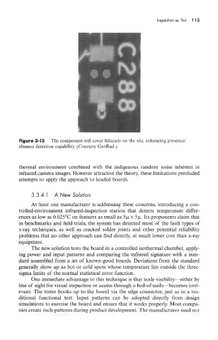
Figure 3-15 The component will cover fiducials on the site, enhancing presence/
absence detection capability. (Courtesy GenRad.)
thermal environment combined with the indigenous random noise inherent in
infrared camera images. However attractive the theory, these limitations precluded
attempts to apply the approach to loaded boards.
3.3.4.1 A New Solution
At least one manufacturer is addressing these concerns, introducing a con-
trolled-environment infrared-inspection station that detects temperature differ-
ences as low as 0.025°C on features as small as 5u × 5 u. Its proponents claim that
in benchmarks and field trials, the system has detected most of the fault types of
x-ray techniques, as well as cracked solder joints and other potential reliability
problems that no other approach can find directly, at much lower cost than x-ray
equipment.
The new solution tests the board in a controlled isothermal chamber, apply-
ing power and input patterns and comparing the infrared signature with a stan-
dard assembled from a set of known-good boards. Deviations from the standard
generally show up as hot or cold spots whose temperature lies outside the three-
sigma limits of the normal statistical error function.
One immediate advantage to this technique is that node visibility—either by
line of sight for visual inspection or access through a bed-of-nails—becomes irrel-
evant. The tester hooks up to the board via the edge connector, just as in a tra-
ditional functional test. Input patterns can be adopted directly from design
simulations to exercise the board and ensure that it works properly. Most compa-
nies create such patterns during product development. The manufacturer need not