
Page 131 - Building A Succesful Board-Test Strategy
P. 131
Inspection as Test 117
availability is still quite limited, however, and the jury is still out on the board types
and factory configurations that will benefit most. Still, by offering a new applica-
tion of an established approach and a way to identify problems that other solu-
tions miss, this technique can provide a viable choice in creating a successful test
strategy.
3.3.5 The New Jerusalem?—X-Ray Inspection
Currently the fastest-growing inspection technique, x-ray inspection can
detect defects that defy the line-of-sight constraint of optical systems. It can
examine hidden components and solder joints on both surfaces of double-sided
boards, and can even inspect inner layers of multilayer boards. X-ray is the only
available technique that can quantitatively analyze solder joints. Results can indi-
cate problems with the solder and assembly processes, measuring such parameters
as solder-joint accuracy, fillet height, solder volume (detecting both insufficient and
excess solder), component existence and position, and polarized-capacitor orien-
tation (by the position of the "slug").
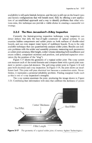
Figure 3-17 shows the geometry of a typical solder joint. The x-ray system
can measure each of the noted features and compare them with a good-joint stan-
dard to permit a pass-fail decision. The gull-wing solder joint in Figure 3-18 will
pass both electrical and x-ray inspection. In Figure 3-19, the joint shows an insuf-
ficient heel. This joint will pass electrical test because a connection exists. Never-
theless, it represents a potential reliability problem. Finding marginal faults such
as this is one of x-ray inspection's strengths.
The x-ray system examines the joint, producing the image shown in Figure
3-20. Combining that information with data that calibrate the darkness of points
Figure 3-17 The geometry of a typical solder joint. (Courtesy Agilent Technologies.)