
Page 133 - Building A Succesful Board-Test Strategy
P. 133
Inspection as Test 119
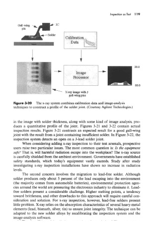
Figure 3-20 The x-ray system combines calibration data and image-analysis
techniques to construct a profile of the solder joint. (Courtesy Agilent Technologies.)
in the image with solder thickness, along with some kind of image analysis, pro-
duces a quantitative profile of the joint. Figures 3-21 and 3-22 contain actual
inspection results. Figure 3-21 contrasts an expected result for a good gull-wing
joint with the result from a joint containing insufficient solder. In Figure 3-22, the
inspection system detects an open on a J-lead solder joint.
When considering adding x-ray inspection to their test arsenals, prospective
users raise two particular issues. The most common question is: Is the equipment
safe? That is, will harmful radiation escape into the workplace? The x-ray source
is carefully shielded from the ambient environment. Governments have established
safety standards, which today's equipment vastly exceeds. Study after study
investigating x-ray inspection installations have shown no increase in radiation
levels.
The second concern involves the migration to lead-free solder. Although
solder produces only about 5 percent of the lead escaping into the environment
(the majority comes from automobile batteries), environmental protection agen-
cies around the world are pressuring the electronics industry to eliminate it. Lead-
free solders present a considerable challenge. Higher melting points, a tendency
toward brittleness, and other drawbacks to this approach will require careful con-
sideration and solution. For x-ray inspection, however, lead-free solders present
little problem. X-ray relies on the absorption characteristics of several heavy-metal
elements (lead, bismuth, silver, tin) to ensure joint integrity. The technique can be
adapted to the new solder alloys by recalibrating the inspection system and the
image-analysis software.