
Page 85 - Building A Succesful Board-Test Strategy
P. 85
Test Methods 71
top side of a clamshell fixture often contacts component legs directly. Pressure from
nails may make an electrical connection when none really exists on the board, so
the test may not notice broken or cold-solder joints.
Although clamshell fixtures present serious drawbacks, they often provide the
only viable way to access a board for in-circuit or MDA test. Because of their com-
plexity, they bring to mind a dog walking on its hind legs: It does not do the job
very well, but, considering the circumstances, you have to be amazed that it can do
the job at all.
Bed-of-nails fixtures permit testing only from nail to nail, not necessarily
from node to node. Consider a small-outline 1C (SOIC) or other surface-mounted
digital component. Actual electrical nodes may be too small for access. For
EGAs and flip-chips, nodes reside underneath. In any case, pads are often
some distance from the actual component under test. Therefore, a trace fault
between the component and the test pad will show up as a component fault,
whereas the continuity test between that pad and the next component or pad
will pass.
Service groups rarely use bed-of-nails systems. Fixtures are expensive and dif-
ficult to maintain at correct revision levels when boards returning from the field
may come from various product versions, some of which the factory may not even
make anymore. Necessary fixture storage space for the number of board types
handled by a service depot would generally be excessive.
Alternatives include foregoing the factory bed-of-nails test altogether to
permit a common test strategy in the factory and the field. Some vendors offer
service testers that can mimic the behavior of their bed-of-nails products without
the need for conventional fixtures. Operation involves scanners, x-y probers, or clips
and probes. These testers can be less expensive than their factory-bound counter-
parts. Software and test programs are compatible or can be converted between the
two machine types.
2.3.6 Bed-of-Nails Probe Considerations
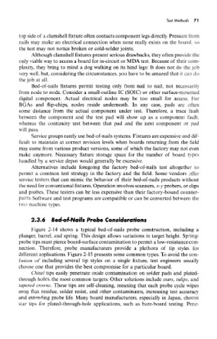
Figure 2-14 shows a typical bed-of-nails probe construction, including a
plunger, barrel, and spring. This design allows variations in target height. Spring-
probe tips must pierce board-surface contamination to permit a low-resistance con-
nection. Therefore, probe manufacturers provide a plethora of tip styles for
different applications. Figure 2-15 presents some common types. To avoid the con-
fusion of including several tip styles on a single fixture, test engineers usually
choose one that provides the best compromise for a particular board.
Chisel tips easily penetrate oxide contamination on solder pads and piated-
through holes, the most common targets. Other solutions include stars, tulips, and
tapered crowns. These tips are self-cleaning, meaning that each probe cycle wipes
away flux residue, solder resist, and other contaminants, increasing test accuracy
and extending probe life. Many board manufacturers, especially in Japan, choose
star tips for plated-through-hole applications, such as bare-board testing. Pene-