
Page 82 - Building A Succesful Board-Test Strategy
P. 82
68 BUILDING A SUCCESSFUL BOARD-TEST STRATEGY
Vcc Vm
o
1
PH A OUT_A
PH B Logic OUT_J3
PH c OUT C
Brake
Thermal
Sensing
I Sense
Control •AA/V—|
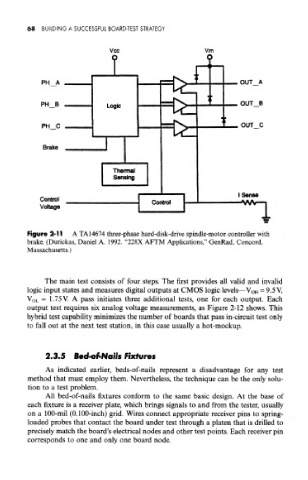
Figure 2-11 A TA14674 three-phase hard-disk-drive spindle-motor controller with
brake. (Durickas, Daniel A. 1992. "228X AFTM Applications," GenRad, Concord,
Massachusetts.)
The main test consists of four steps. The first provides all valid and invalid
logic input states and measures digital outputs at CMOS logic levels—V OH = 9.5 V,
VOL = 1.75V. A pass initiates three additional tests, one for each output. Each
output test requires six analog voltage measurements, as Figure 2-12 shows. This
hybrid test capability minimizes the number of boards that pass in-circuit test only
to fall out at the next test station, in this case usually a hot-mockup.
2.3.5 Bed-of-Nails Fixtures
As indicated earlier, beds-of-nails represent a disadvantage for any test
method that must employ them. Nevertheless, the technique can be the only solu-
tion to a test problem.
All bed-of-nails fixtures conform to the same basic design. At the base of
each fixture is a receiver plate, which brings signals to and from the tester, usually
on a 100-mil (0.100-inch) grid. Wires connect appropriate receiver pins to spring-
loaded probes that contact the board under test through a platen that is drilled to
precisely match the board's electrical nodes and other test points. Each receiver pin
corresponds to one and only one board node.