
Page 79 - Building A Succesful Board-Test Strategy
P. 79
Test Methods 65
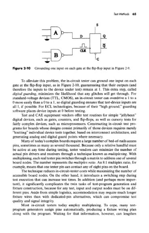
Figure 2-10 Grounding one input on each gate at the flip-flop input in Figure 2-9.
To alleviate this problem, the in-circuit tester can ground one input on each
gate at the flip-flop input, as in Figure 2-10, guaranteeing that their outputs (and
therefore the inputs to the device under test) remain at 1. This extra step, called
digital guarding, minimizes the likelihood that any glitches will get through. For
standard-voltage devices (TTL, CMOS), an in-circuit tester can overdrive a 1 to a
0 more easily than a 0 to a 1, so digital guarding ensures that test-device inputs are
all 1, if possible. For ECL technologies, because of their "high ground," guarding
software places device inputs at 0 before testing.
Test and CAE equipment vendors offer test routines for simple "jellybean"
digital devices, such as gates, counters, and flip-flops, as well as cursory tests for
fairly complex devices, such as microprocessors. Constructing in-circuit test pro-
grams for boards whose designs consist primarily of those devices requires merely
"knitting" individual device tests together, based on interconnect architecture, and
generating analog and digital guard points where necessary.
Many of today's complex boards require a large number of bed-of-nails access
pins, sometimes as many as several thousand. Because only a relative handful must
be active at any time during testing, tester vendors can minimize the number of
actual pin drivers and receivers through a technique known as multiplexing. With
multiplexing, each real tester pin switches through a matrix to address one of several
board nodes. The number represents the multiplex ratio. An 8:1 multiplex ratio, for
example, means that one tester pin can contact any of eight pins on the board.
The technique reduces in-circuit-tester costs while maximizing the number of
accessible board nodes. On the other hand, it introduces a switching step during
test execution that can increase test times. In addition (and perhaps more impor-
tant), it significantly complicates the twin tasks of test-program generation and
fixture construction, because for any test, input and output nodes must be on dif-
ferent pins. Aside from simple logistics, accommodation may require much longer
fixture wires than with dedicated-pin alternatives, which can compromise test
quality and signal integrity.
Most in-circuit testers today employ multiplexing. To cope, many test-
program generators assign pins automatically, producing a fixture wiring plan
along with the program. Waiting for that information, however, can lengthen