
Page 77 - Building A Succesful Board-Test Strategy
P. 77
Tesf Methods 63
10 kQ
vw
Source ^ ^, ^ ~ 3 x Measure
R = 10 kQ
M
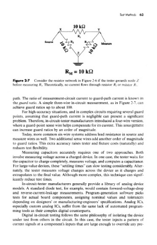
Figure 2-7 Consider the resistor network in Figure 2-6 if the tester grounds node Z
before measuring RI. Theoretically, no current flows through resistor R 2 or resistor R 3.
path. The ratio of measurement-circuit current to guard-path current is known as
the guard ratio. A simple three-wire in-circuit measurement, as in Figure 2-7. can
achieve guard ratios up to about 100.
For high-accuracy situations, and in complex circuits requiring several guard
points, assuming that guard-path current is negligible can present a significant
problem. Therefore, in-circuit-tester manufacturers introduced a four-wire version,
where a guard-point sense wire helps compensate for its current. This arrangement
can increase guard ratios by an order of magnitude.
Today, more common six-wire systems address lead resistance in source and
measure wires as well. Two additional sense wires add another order of magnitude
to guard ratios. This extra accuracy raises tester and fixture costs (naturally) and
reduces test flexibility.
Measuring capacitors accurately requires one of two approaches. Both
involve measuring voltage across a charged device. In one case, the tester waits for
the capacitor to charge completely, measures voltage, and computes a capacitance.
For large-value devices, these "settling times" can slow testing considerably. Alter-
nately, the tester measures voltage changes across the device as it charges and
extrapolates to the final value. Although more complex, this technique can signif-
icantly reduce test times.
In-circuit-tester manufacturers generally provide a library of analog device
models. A standard diode test, for example, would contain forward-voltage-drop
and reverse-current-leakage measurements. Program-generation software picks
tests for actual board components, assigning nominal values and tolerances
depending on designers' or manufacturing-engineers' specifications. Analog ICs,
especially custom analog ICs, suffer from the same lack of automated program-
ming tools as their complex digital counterparts.
Digital in-circuit testing follows the same philosophy of isolating the device
under test from others in the circuit. In this case, the tester injects a pattern of
current signals at a component's inputs that are large enough to override any pre-