
Page 169 - Buried Pipe Design
P. 169
Design of Gravity Flow Pipes 143
where E′ traditional soil modulus
E′ eff effective soil modulus
H height of cover
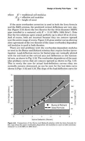
If the same overburden correction is used in both the Iowa formula
and the B&R solution, the predicted vertical deflections are very sim-
ilar. Figure 3.34 shows the two theories for the 48-in-diameter HDPE
2
pipe installed in a material with E′ 11.02 MPa (1600 lb/in ). Note
that the two solutions agree almost perfectly up to about 25 m of cover.
And of course, both are incorrect because they are concave upward
over the entire range of covers. Figure 3.35 gives similar curves showing
close agreement of the two theories if the same overburden-dependent
soil modulus is used in both theories.
There are real problems with the overburden-dependent modulus
as used in the Burns and Richard solution that require further inves-
tigation. Load-deflection curves for buried pipe are normally plotted
with the soil load on the vertical axis and deflection on the horizon-
tal axis, as shown in Fig. 3.32. The overburden dependence of the mod-
ulus produces curves that are concave upward as shown in Fig. 3.35.
This is rarely the case for actual load-deflection curves—they are
normally concave downward, as can be seen for the test data curve
shown in Figs. 3.32 and 3.33. The slope of the load-deflection curve for
Cover Height (Meters) Cover Height (Feet)
Burns & Richard
Iowa Formula
Vertical Deflection (Percent)
Figure 3.34 Comparison of the Burns and Richard solution with the Iowa formula for
the case when the same overburden-dependent soil modulus is used in both solutions.
2
Initial E′ is 11.02 MPa or 1600 lb/in .