
Page 268 - Buried Pipe Design
P. 268
Design of Pressure Pipes 239
forces are generally insignificant in relation to the hydrostatic thrust
forces and are usually ignored. Simply stated, thrust forces occur at
any point in the piping system where the direction or cross-sectional
area of the waterway changes. Thus, there will be thrust forces at
bends, reducers, offsets, tees, wyes, dead ends, and valves.
Balancing thrust forces in underground pipelines is usually accom-
plished with bearing or gravity thrust blocks, restrained joint systems,
or combinations of these methods. The internal hydrostatic pressure
acts perpendicularly on any plane with a force equal to the pressure P
times the area A of the plane. All components of these forces, acting
radially within a pipe, are balanced by circumferential tension in the
wall of the pipe. Axial components acting on a plane perpendicular to
the pipe through a straight section of the pipe are balanced internally
by the force acting on each side of the plane. Consider, however, the
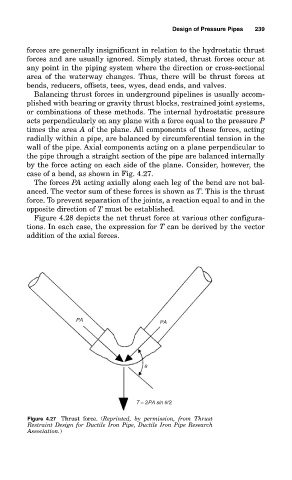
case of a bend, as shown in Fig. 4.27.
The forces PA acting axially along each leg of the bend are not bal-
anced. The vector sum of these forces is shown as T. This is the thrust
force. To prevent separation of the joints, a reaction equal to and in the
opposite direction of T must be established.
Figure 4.28 depicts the net thrust force at various other configura-
tions. In each case, the expression for T can be derived by the vector
addition of the axial forces.
PA
PA
q
T = 2PA sin q/2
Figure 4.27 Thrust force. (Reprinted, by permission, from Thrust
Restraint Design for Ductile Iron Pipe, Ductile Iron Pipe Research
Association.)