
Page 269 - Buried Pipe Design
P. 269
240 Chapter Four
PA r
T = PA
b T = PA
PA PA
b
Dead end
PA r
PA r
Tee
T = PA b
PA 2 PA 1
PA
b
T = P (A –A )
1
2
PA
Reducer r
Wye
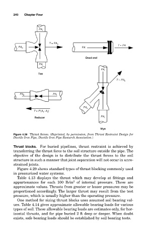
Figure 4.28 Thrust forces. (Reprinted, by permission, from Thrust Restraint Design for
Ductile Iron Pipe, Ductile Iron Pipe Research Association.)
Thrust blocks. For buried pipelines, thrust restraint is achieved by
transferring the thrust force to the soil structure outside the pipe. The
objective of the design is to distribute the thrust forces to the soil
structure in such a manner that joint separation will not occur in unre-
strained joints.
Figure 4.29 shows standard types of thrust blocking commonly used
in pressurized water systems.
Table 4.13 displays the thrust which may develop at fittings and
2
appurtenances for each 100 lb/in of internal pressure. These are
approximate values. Thrusts from greater or lesser pressures may be
proportioned accordingly. The larger thrust may result from the test
pressure, which is usually higher than the operating pressure.
One method for sizing thrust blocks uses assumed soil bearing val-
ues. Table 4.14 gives approximate allowable bearing loads for various
types of soil. These allowable bearing loads are estimates only, for hor-
izontal thrusts, and for pipe buried 2 ft deep or deeper. When doubt
exists, safe bearing loads should be established by soil bearing tests.