
Page 271 - Buried Pipe Design
P. 271
242 Chapter Four
TABLE 4.14 Estimated Bearing Load
Soil type lb/ft 2
Muck, peat, etc. 0
Soft clay 500
Sand 1000
Sand and gravel 1500
Sand and gravel with clay 2000
Sand and gravel cemented with clay 4000
Hard pan 5000
The design calculation of a thrust block is illustrated in the next
example
Example Problem 4.3 Required is thrust block at 10-in 90 elbow.
Maximum test pressure is 200 lb/in . Soil type is sand and gravel with clay.
2
■ Calculate thrust. From Table 4.13, thrust on 10-in 90 elbow is 13,680 lb
per 100 lb/in operating pressure. Total thrust 2 (13,680) 27,360 lb.
2
■ Calculate thrust block size. From Table 4.14, safe bearing load for sand and
gravel and clay is 2000 lb/ft ; total thrust support area 27,360/2000
2
2
13.68 ft .
■ Select type of thrust block. From Fig. 4.29, select type 3.
Restrained joints. An alternate method of thrust restraint uses
restrained joints. Various mechanical locking-type joints are available
to provide longitudinal restraint. Of course, a welded steel joint is con-
sidered to be rigid and provides maximum longitudinal restraints.
Restrained joint systems are subjected to the same thrust forces, but
these forces are resisted or distributed over the restrained pipe length.
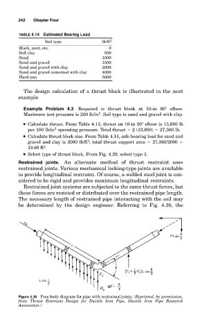
The necessary length of restrained pipe interacting with the soil may
be determined by the design engineer. Referring to Fig. 4.30, the
PA
PA
L
[ F s + R s L ]
F s
L cos 1
2
R s
Figure 4.30 Free-body diagram for pipe with restrained joints. (Reprinted, by permission,
from Thrust Restraint Design for Ductile Iron Pipe, Ductile Iron Pipe Research
Association.)