
Page 323 - Buried Pipe Design
P. 323
294 Chapter Six
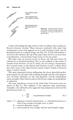
Spot-welded seam
initially
Spot-welded seam
as it begins to hinge
Spot-welded seam
as hinge starts to
flow Figure 6.8 Diagrammatic sketch
of welded seam showing typical
formation of hinge followed by
plastic flow.
Under soil loading the pipe tends to form an ellipse, but in doing so,
flexural stresses develop. These stresses combined with some ring
compression cause what appears to be a wall crushing, which may be
described better as a plastic hinge (see Fig. 6.8). If this deformation is
carried to the extreme, the top of the pipe comes down in an inversion,
and ultimately a third plastic hinge forms in the top center.
The other type of reversal occurs in dense soil and may better be
referred to as localized buckling. This is not confined to top center. It
usually forms between 10 and 2 o’clock, but not always. Occasionally,
the reversal occurs in the bottom half between 5 and 7 o’clock. None
have been seen in the sides between about 2 and 5 o’clock or between
about 7 and 10 o’clock.
The most important factors influencing the above described perfor-
mance limits are the pipe wall crushing strength and the soil compres-
sion. Of lesser influence are the ring flexibility and the longitudinal
seam strength. Other factors such as soil friction angle are insignificant
or unknown.
The most significant results of the Utah State University tests are
shown in Fig. 6.4. The ordinate is the apparent ring compression
strength f . It is defined as the apparent ring compression stress at the
c
performance limit, i.e.,
PD
f c at performance limit (6.1)
2A
where P apparent vertical soil pressure, i.e., calculated pressure at
level of top of pipe if no pipe were in place
D nominal diameter of pipe
A cross-sectional area of pipe wall per unit length of pipe