
Page 322 - Buried Pipe Design
P. 322
Steel and Ductile Iron Flexible Pipe Products 293
limit for deep corrugations tends to be plastic hinges at the sides rather
than reversed curvature. For shallow corrugation, plastic hinges at the
sides form only if the soil is very compressible; otherwise, the perfor-
mance limit is reversal of curvature. The difference is insignificant in
light of uncertainties in soil placement, density, or boundaries.
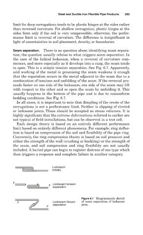
Seam separation. There is no question about identifying seam separa-
tion; the question usually relates to what triggers seam separation. In
the case of the helical lockseam, when a reversal of curvature com-
mences, and more especially as it develops into a cusp, the seam tends
to open. This is a simple tension separation. See Fig. 6.7. Apparently,
cold working of the metal in processing the seam weakens it enough
that the separation occurs in the metal adjacent to the seam due to a
combination of tensions and unfolding of the seam. If the reversal pro-
ceeds faster on one side of the lockseam, one side of the seam may lift
with respect to the other and so open the seam by unfolding it. This
usually happens in the bottom of the pipe and is due to nonuniform
bedding conditions. See Fig. 6.7.
In all cases, it is important to note that dimpling of the crests of the
corrugations is not a performance limit. Neither is slipping of riveted
or lockseam joints. These should be accepted as stress relievers. It is
highly significant that the extreme deformations referred to earlier are
not typical of field installations, but can be observed in a test cell.
Each design theory is based on an entirely different performance
limit based on entirely different phenomena. For example, ring deflec-
tion is based on compression of the soil and flexibility of the pipe ring.
Conversely, the ring compression theory is based on soil pressure and
either the strength of the wall (crushing or buckling) or the strength of
the seam, and soil compression and ring flexibility are not usually
included. A buried pipe can begin to register distress of one type which
then triggers a response and complete failure in another category.
Lockseam
initially
F Lockseam tension
F
separation
Figure 6.7 Diagrammatic sketch
F Lockseam flexure of seam separation of lockseam
separation joint.
F