
Page 35 - Buried Pipe Design
P. 35
External Loads 13
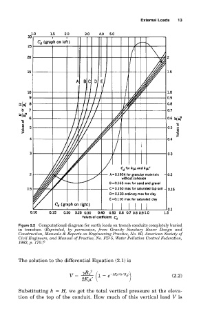
Figure 2.2 Computational diagram for earth loads on trench conduits completely buried
in trenches. (Reprinted, by permission, from Gravity Sanitary Sewer Design and
Construction, Manuals & Reports on Engineering Practice, No. 60, American Society of
Civil Engineers, and Manual of Practice, No. FD-5, Water Pollution Control Federation,
1982, p. 170.) 6
The solution to the differential Equation (2.1) is
2
B d 2K ′(h/B )
V 1 e d (2.2)
2K ′
Substituting h H, we get the total vertical pressure at the eleva-
tion of the top of the conduit. How much of this vertical load V is