
Page 36 - Buried Pipe Design
P. 36
14 Chapter Two
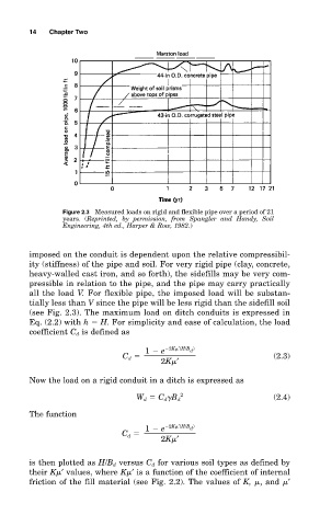
Figure 2.3 Measured loads on rigid and flexible pipe over a period of 21
years. (Reprinted, by permission, from Spangler and Handy, Soil
Engineering, 4th ed., Harper & Row, 1982.)
imposed on the conduit is dependent upon the relative compressibil-
ity (stiffness) of the pipe and soil. For very rigid pipe (clay, concrete,
heavy-walled cast iron, and so forth), the sidefills may be very com-
pressible in relation to the pipe, and the pipe may carry practically
all the load V. For flexible pipe, the imposed load will be substan-
tially less than V since the pipe will be less rigid than the sidefill soil
(see Fig. 2.3). The maximum load on ditch conduits is expressed in
Eq. (2.2) with h H. For simplicity and ease of calculation, the load
coefficient C d is defined as
1 e 2K ′(H/B )
d
C d (2.3)
2K ′
Now the load on a rigid conduit in a ditch is expressed as
2
W d C d B d (2.4)
The function
1 e 2K ′(H/B )
d
C
2K ′
d
is then plotted as H/B d versus C d for various soil types as defined by
their K ′ values, where K ′ is a function of the coefficient of internal
friction of the fill material (see Fig. 2.2). The values of K, , and ′