
Page 72 - Buried Pipe Design
P. 72
48 Chapter Two
f′ f′
f′ Angle of Repose
Void
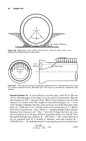
Figure 2.26 Rigid pipe cross section showing how voids are left if soil is not
deliberately placed under the haunches.
Live Load
P
Q
Reaction Bell Shard
Reaction
Figure 2.27 Bell end of a section of rigid pipe subjected to live load pressure, but acting
as a simply supported beam. Reactions Q at the ends are provided by contiguous pipe
sections.
Example Problem 2.6 A nonreinforced concrete pipe, with ID of 380 mm
(15 in), bell and spigot, C-14, class 3, is to be used as a storm drain. The out-
side diameter is OD 480 mm (19 in). What is the minimum cover H if the
fracture is a broken bell? The length of nonreinforced pipes is L 2.4 m
(8 ft). Assume (estimate) that the cross-sectional area of the thin part of the
bell is A 3230 mm (5 in ). Tensile stress at the spring lines is Q/(2A),
2
2
from which maximum Q 2A f , where f tensile strength of the concrete.
Reaction Q at fracture is Q 2A f 44.5 kN (10 kips). But Q is the reac-
tion to pressure P l on the pipe which is caused by surface live load W. From
2
the punch-through cone analysis, P l 4W/ (32 in H) . Conservatively, it
can be assumed that W is located at midspan, and that reaction Q
0.5P(OD)(32 in H). Substituting for P and equating the two Q values give
W (OD)
A f (2.20)
(32 in H)