
Page 67 - Buried Pipe Design
P. 67
External Loads 43
W
1
L
2
B
H
(L+H )
M = 0.022 Pr 2
(B+H) Maximum
Moment
12°
μ μ
μ = 45°
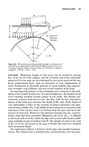
Figure 2.23 Truncated pyramid punched through a minimum soil
cover H by an approaching wheel load W. Shear planes form on a
1:2 slope. Typical angles are less than 45°. Pressure is approx-
imately P W/[(B H)(L H)].
Live load. Minimum height of soil cover can be found by solving
Eq. (2.15) for H if the surface load W is known and if the allowable
pressure P on the pipe can be evaluated for any given pipe and for any
given performance limit, such as inversion or ring compression at
yield. Evaluation of allowable pressure P must include ring compres-
sion strength, ring stiffness, and the critical location of the load.
An unsuspected problem in the minimum-cover analysis is the defi-
nition of the height of soil cover. For paved highways, the height of soil
cover remains constant during passes of live loads. But during con-
struction, a heavy load leaves ruts. See Fig. 2.24. In fact, successive
passes of the load may increase the depth of the ruts. If the depth of
ruts approaches a limit as the number of passes increases, the pipe-
soil system is stable. But if the depth of ruts continues to increase with
each pass of the surface load, it is obvious that the pipe may be in the
process of inversion. Whatever the ultimate damage may be, a perfor-
) is defined
mance limit has been exceeded. Minimum soil cover (H min
as the least soil cover for which the pipe-soil system will remain stable
upon multiple passes of surface load W. The height of cover to be used
in Eq. (2.15) for soil stress on the pipe is H after the ruts have reached
their maximum depth.
For rigid pipes, failure is fracture of the pipe and possible fragmen-
tation. The critical load is located either symmetrically over the pipe,