
Page 69 - Buried Pipe Design
P. 69
External Loads 45
P Maximum
P
Moment
A
12°
45° 45° 45° 45°
Free-Body Diagram Plastic Hinging
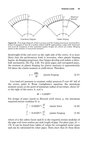
Figure 2.25 Free-body diagram of the inversion arch for finding maximum moment M in
terms of pressure P due to a surface wheel load W approaching a pipe with minimum
soil cover H. Locations of four potential plastic hinges are shown as circles. Hinging
starts at the location of maximum moment.
deadweight of the soil cover on the right side of the crown. It is more
likely that the performance limit is inversion, when plastic hinging
begins. As hinging progresses, four hinges develop and isolate a three-
link mechanism. See Fig. 2.25. For plain pipes and corrugated pipes,
the moment at plastic hinging (by plastic analysis) is approximately
3/2 times the elastic moment at yield stress. Therefore,
2Mc
plastic hinging (2.17)
3I
Live load soil pressure is constant radial pressure P over 45° left of
the crown, point A. From Castigliano’s equation, the maximum
moment occurs at the point of minimum radius of curvature, about 12°
to the right of the crown A, and is
M 0.022Pr 2
For design of pipes based on flexural yield stress f , the minimum
required section modulus I/c is
I sf
2
(0.022Pr ) elastic limit (2.18)
c f
I sf
2
(0.015Pr ) plastic hinging (2.19)
c f
where sf is the safety factor and I/c is the required section modulus of
the pipe wall cross section per unit length of pipe. For plain pipe, I/c
2
t /6. It can be found from tables of values for corrugated metal pipes
and can be calculated for other pipes. Tests show that I/c from these