
Page 68 - Buried Pipe Design
P. 68
44 Chapter Two
Motion
Dual
Wheel
Rut H¢¢ W
H
H¢
c
A = Area of Pipe
Wall Per Unit
Length of
Pipe
D
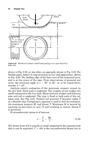
Figure 2.24 Sketch of a surface wheel load passing over a pipe buried in
loose soil.
shown in Fig. 2.22, or, less often, on approach, shown in Fig. 2.23. For
flexible pipes, failure is ring inversion as live load approaches, shown
in Fig. 2.23. The leading edge of the base area of the truncated pyra-
mid is at the crown of the pipe. From observations of granular soil
cover, the inversion angle is 30° to 40°, or, to be conservative,
assume 45°.
Analysis entails evaluation of the maximum moment caused by
the live load. Dead load is neglected. The weights of soil wedges are
small compared to the live load. Shear between wedges and between
pipe and soil is neglected. The ring is fixed at both ends of the col-
lapse arch. See Fig. 2.25. Vertical soil pressure P becomes radial P
on a flexible ring. Castigliano’s equation is used to find the reactions,
the maximum moment M, and thrust T. Maximum M is located by
equating its derivative to zero. If wall crushing is critical, thrust T
is pertinent.
If circumferential stress is of interest,
T Mc
(2.16)
A I
The thrust term T/A is usually so small compared to the moment term
that it can be neglected. T Hr is the circumferential thrust due to