
Page 66 - Buried Pipe Design
P. 66
42 Chapter Two
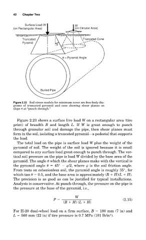
Surface Load W W
(on Rectangular Area) (on Circular Area)
Truncated Truncated Cone
Pyramid
θ
θ = Pyramid Angle
Buried Pipe
Figure 2.22 Soil stress models for minimum cover are free-body dia-
grams of truncated pyramid and cone showing shear planes on
slope at “punch-through.”
Figure 2.23 shows a surface live load W on a rectangular area (tire
print) of breadth B and length L. If W is great enough to punch
through granular soil and damage the pipe, then shear planes must
form in the soil, isolating a truncated pyramid—a pedestal that supports
the load.
The total load on the pipe is surface load W plus the weight of the
pyramid of soil. The weight of the soil is ignored because it is small
compared to any surface load great enough to punch through. The ver-
tical soil pressure on the pipe is load W divided by the base area of the
pyramid. The angle which the shear planes make with the vertical is
the pyramid angle 45° /2, where is the soil friction angle.
From tests on cohesionless soil, the pyramid angle is roughly 35°, for
which tan 0.5, and the base area is approximately (B H)(L H).
The precision is as good as can be justified for typical installations.
Analysis is conservative. At punch-through, the pressure on the pipe is
the pressure at the base of the pyramid, i.e.,
W
P (2.15)
(B H) (L H)
For H-20 dual-wheel load on a firm surface, B 180 mm (7 in) and
2
L 560 mm (22 in) if tire pressure is 0.7 MPa (101 lb/in ).