Page 136 - CNC Robotics
P. 136

Chapter 5 / Software Setup and Driver Test


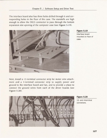
          The interface board also has three holes drilled through it and cor-
          responding holes in the floor of the case. The standoffs are high
          enough to allow the 0825 connector to pass through the bottom
          expansion slot opening of th e computer case (see Figure 5.19).

                                                                           Figure 5.19
                                                                           Interface board
                                                                           mounted on floor of
                                                                           case.


          Next . install a 12-term inal connector strip for motor w ire attach-
          ment and a 4- termi nal connecto r strip to supply power and
          ground to the interface board and fan . and to provide a place to
          connect the ground wires from each of the driver boa rds (see
          Figure 5.20).


                                                                           Figure 5.20
                                                                           12- and 4-term inal
                                                                           connectors.


                                                                                           127
   131   132   133   134   135   136   137   138   139   140   141