
Page 137 - CNC Robotics
P. 137
CNC Robotics
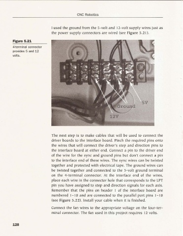
I used the ground from the 5-volt and 12-volt supply wires just as
the power supply connectors are wired (see Figure 5.21).
Figure 5.21
4-terminal connector
provides 5 and 12
volts.
The next step is to make cables that will be used to connect the
driver boards to the interface board. Pinch the required pin s onto
the wires that will connect the driver 's step a nd direction pins to
the interface board at either end. Connect a pin to the driver end
of the wire for the syn c and ground pin s but don 't connect a pin
to the interface end of the se wire s. The sy nc wires ca n be twisted
together and protected with electrical tape. The ground wires can
be twisted together and connected to the 5-volt ground terminal
on the 4-terminal connector. At the interface end of the wires,
place each wire in the connector hole that cor res ponds to the LPT
pin you have assigned to step and directio n sig nals for eac h axis.
Remember that the pin s on header I of the inter face board are
numbered 1- I8 and are connected to the parallel po rt pin s 1-18
(see Figure 5. 22). Install your cabl e whe n it is finished.
Connect the fan wires to the appropriate voltage on the fou r-ter-
minal connector. The fan used in this project requ ires 12 volts.
128