
Page 218 - CNC Robotics
P. 218
Chapter 9 / Motor and Lead Screw Installation
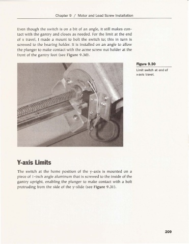
Even though the switch is on a bit of an angle. it still ma kes con-
tact with the gantry and closes as nee ded. For the limit at the end
of x travel. I made a mount to bolt the swi tch to; th is in turn is
screwed to the bearing ho lder. It is insta lled on an angle to allow
the plunger to make contact with the ac me screw nut holder at the
front of the gantry foot (see Figure 9.30).
Figure 9.30
Limit switch at end of
x-axis trave l.
Y-axis Limits
The switch at the home position of the y-axis is mounted on a
piece of l-Inch angle aluminum that is screwed to the inside of the
gantry upright. enabli ng the plunger to make contact with a bolt
protruding from the side of the y-sli de (see Figure 9.31).
209