
Page 222 - CNC Robotics
P. 222
Chapter 9 / Motor and Lead Screw Installation
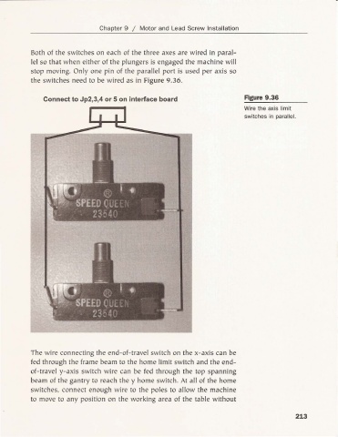
Both of the switches on each of the th ree axes are w ired in paral-
lel so that w hen either of the plungers is engaged the machi ne w ill
stop moving. Only one pin of the paralle l port is used per axis so
the switches need to be wired as in Fig ure 9.36.
Connect to Jp2,3,4 or 5 on interface board Figure 9.36
Wire the axis limit
switches in parallel.
The wire connecting the end-of-travel switch on the x-axis can be
fed through the frame beam to the home limit switch and the end-
of-travel y- axis switch wire can be fed through the top spanning
beam of the gantry to reach the y home switch. At all of the home
switches. connect enough wire to the poles to allow the machine
to move to any position on the working area of the table without
213