
Page 227 - CNC Robotics
P. 227
eNG Robotics
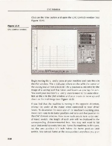
Click on the View button and open th e CNC Controls window (see
Figure 10.4).
Figure 10.4 _I",,,,
eNC Controls window.
8 ~ f'~
:.~
;&
"C
L
,~ --
I
Begin moving the X '- and y-axes of your machine and note the x in
the plot w indow. The x indicates w here on the tab le the center of
the cutting tool or pen is located. The z position is ind icated by the
ima ge of a cutting tool that raises and lowers as yo u jog the axis.
You want your machine's x- and y-axes to move in the same direc-
tion as the x in the pl ot window and your z-axis to move up and
dow n as the tool image (see Figure 10.5).
If you find tha t the machine is movin g in the opposite direction,
reverse the order of the motor wires connected to your driver
board. To determine the exact size of the machine's working area,
move each axis to its home positi on and zero out that posi tion in
the CNC Controls window. Now move each axi s in turn to the end -
of-travel switch. The length of each axis w ill be displayed in th e
correspo nding distance-traveled box . You may not wa nt to hit
yo ur limit switch es every time you home the machine; in this case,
set the zero positi on 1/ 4-inch before the home position limit
switch. You can set hom e or the zero pos ition anyw here yo u pre-
218