
Page 225 - CNC Robotics
P. 225
CNC Robotics
Figure 10.1 ... ~ - :..J<Ul
:...JgW
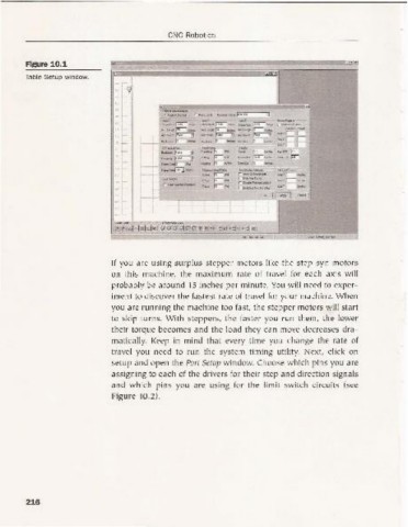
Table Setup window.
"r E~;,,===-· ... r __ . ""
,.
"
r. __
-,
....._p.iJ"s- -.-. ~~
-~--
" " - , - , "_~f_piioxu 3 --
r v_~
... _~ _~ ~ _ -- 4t>~_ ....Xl - '- r:
,
l ..
_
-~~-
...-----J
~_
... _
~ !_~- -- ~ eod_ .-- - " ,
Xy.-.dz.... - .- ..--
;::: -~ T~'jlr-... -" Ii'
..~
e---------+---l "-.. ~ "- rr.... _c.../iT_ _A!~
f1....s..or ... _ ra--~..... ...~ .--
_r...._
r- -- ~1IW/iOO3"""'" .- .... ~f_ ...tOOl"""'"
-
_xr---
r_z,-*,-
r _ _ CInot
" - ~~ r;;-.... rOoMtOt __ .....vr-_
rLaO__
r-r- ~ ,- jii""""" ... _zr-_
- >------t-i ,- pr-AI r (_z.....Jog--..
~ ~ I ~ C-.c" i
, - '----+-
,
, ! t -; f--
~
~.- :{) ~ T"'"
!
r~1 ~12 !t." !~ 1~·' 1~ @16!BI@B!51!@!tilhp 3 ufii)3 vf\"iiil .:::J
SolO~d___
I WJ9Cf04li,;o,
If you are using surplus stepper motor s li ke the step-syn motors
on this machine, the maximum rate of travel for each axis w ill
probably be around 15 inches per minute. You w ill need to exper-
iment to di scover the fastest rate of travel for your machine. When
you are running the machine too fast, the step per motors w il l start
to skip turns. With steppers, the faster you ru n them, th e lower
their torqu e becomes and the load they can move decreases dra -
mati call y. Keep in mind that every time you change the rate of
trave l you need to run the system timing ut il ity. Next , click on
setup and ope n the Port Setup w indow. Choose w hich pins yo u are
assigning to each of the drivers for their step and direct ion signals
and w hich pins you are using for the limit switch circuits (see
Figure 10.2).
216