
Page 220 - CNC Robotics
P. 220
Chapter 9 / Motor and Lead Screw Installation
Z-axis Limits
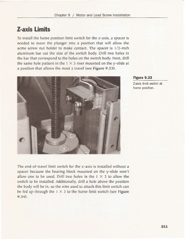
To insta ll the home posit ion limit sw itch for the z-axls, a spacer is
needed to move the plunger into a position that will allow the
acme screw nut holder to make co ntact. The spacer is 1/2- inc h
alum inum ba r cut the size of the switch body. Drill two holes in
the ba r that co rrespond to the holes on the sw itch body. Next, dr ill
the same hole pattern in the I X 3 riser mounted on the y-sll de at
a position that allows the most z travel (see Figure 9.33).
Figure 9.33
Z-axis limit switch at
home position.
The end-of- trave l limit switch for the z-ax is is installed wit hout a
spacer beca use the bea ring block mou nted on the y-sllde wo n't
allow one to be used. Drill two holes in the I X 3 to allow the
switch to be installed. Additionally. drill a hole above the posit ion
the body will be in. so the wire used to attac h this limit switch ca n
be fed up through the I X 3 to the home limit switch (see Figu re
9.34).
211