
Page 81 - CNC Robotics
P. 81
CNC Robotics
APPUCATION NOTE
PBL3717A, the noise spike fools the comparator ping circuit is to stop the motor movement (hold
and retriggers the monostable effectively multiply- the clock of the l297 low or hold the four inputs
ing the set off time by some integer value. constant with the L6506) and look at the current
wave forms without any effects of the phase
Two easy solutions to this problem are possible.
The first is to put a simple RC low pass filter be- changes. This evaluation should be done for each
tween the sense resistor and the sense input of level of current that will be regulated . A DC cur-
the comparator. The filter attenuates the spike so rent probe,like the Tektron ix AMS03 system, pro-
it is not detected by the comparator. This obvi- vides the most accurate representation of the mo-
ously requires the addition of 4 additional compo- tor current. If the circuit is operating stability, the
nents for a typical stepper motor. The second so- current wave form will be synch ronized to the
lution is to use the inherent set dominance of the sync signal of the control circuit. Since the spikes
internal flip-flop in the L297 or L6506 [1][3J to discussed previously are extremely short, in the
mask out the spike. To do this the width of the os- range of 50 to 150 ns, a high frequency scope
ci1latorsync pulse is set to be longer than the sum with a bandwidth of at least 200 MHz is required
of the propagatio ndelay (typically 2 to 31ls for the to evaluate the clrcult. The sync signal to the
L298N) plus the duration of the spike (usually in L297 or L6506 provides the best trigger for the
the range of 1DOns for acceptable fast recovery scope.
diodes),as shown in figure 12. When this pulse is The other issue that affects the stability of the
applied to the flip-flop set input,any signal applied constant frequency PWM circuits is the chopping
to the reset input by the comparator is ignored. mode selected. With the l297 the choppingsignal
After the set input has been removed the compa- may be applied to either the enable inputs or the
rator can property reset the f1ip-tiop at the correct four phase inputs. When chopping is done using
point. the enable inputs the recircufation path for the
The corresponding solution in frequency modu- current is from ground through the lower recircu-
lated circuits, is to fix a blanking time during which lation diode, the load, the upper recirculation di-
the monostable may net be retriggered. ode and back to the supply, as shown in Flqure
Be. This same recirculation path is achieved using
The best way to evaluate the stab ility of the chop-
two phase chopping, although this may not be im-
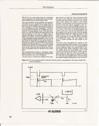
Figure 12: The set-dominanct latch in the L297 may be used to mask spikes on the sense resistor that
occur at switching.
9/12
- --- - - - ---- J.Ti==:= - - - --- - ---'--'=
72
r-