
Page 78 - CNC Robotics
P. 78
Chapter 2 / Electronics
APPLICATION NOTE
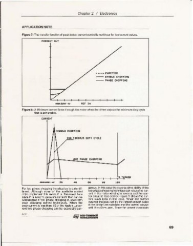
Figure 7: The transfer function of peak detect current control is nonlinear for low current values.
CURRENT OUT
• •••• EXPECTED
---- ENABLE CHOpPING
---- PHASE CHOPpIHG
.. .. ..
REF 1M
Figure 8: A MinilTl.lrn current flows through the motor when the driver outputs the min imum duty cycle
that is achievable.
CURRENT
EHABLE C"'OPPIHG
tSI MINIMUM DUTY CYCLE
,..
L..---.,f---l-_-+_+_+----.,f--+_-+_+_+.!..2T~Cho••
A. 68 8.
For two phase chopping the situation is quite dif- gerous. In this case the reverse drive ability of the
ferent. Although none of the available control two phase chopping techniqu e can cause the cu r-
chips implement this mode it is discussed here rent in the motor windi ng to reverse and the con-
since it is easy to generate currents that can be trol circ uit to lose control. Figure 9 shows the cu r-
catastrophic if two phase chopping is used with rent wave form in this case . When the current
peak detecting control techniques. When the reaches the peak set by the reference both sides
pea k current is less than 1/2 of the ripple (I pp ) cur- of t,h~ bridge are switched and the current decays
rent two phase chopping can be espe cially dan - until it reache s zero. SlOce the power transistors
JIij-'-'-' - - - - ---- - -
6112
69