
Page 74 - CNC Robotics
P. 74
r- - - - - - - - - - - - - - - - - - - - - - - - - - - - - - - - - - --- - - - -
Chapter 2 / Electron ics
APPLICATION NOTE
higher voltage is used and the current limit is set
Figure 2: Direct voltage drive.
A- low speed; by an external resistor in series with the motor
B • too high speed generates fall of winding such that the sum of the external resis-
tance and the internal winding resistance limits
torq ue.
the current to the allowed value . This drive tech-
nique increases the current slew rate and typically
provides better torque at high rotational speed.
However there is a significant penalty paid In ad-
• ditional dissipation in the extemal resistances.
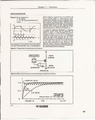
To avoid the additional dissipation a chopping
controlled current drive may be employed , as
shown in Figure 3. In th is technique the current
through the motor is sensed and controlled by a
choppi ng control circu it so that it is maintained
within the rated level. Devices like the L297.
8 L6506 and PBL3717A implement this type of con-
,
- - - -- - trol. This technique improves the current rise time
in the motor and improves the torque at high
speeds while maintaining a high efficiency in the
drive {2]. Figure 4 shows a comparison between
One solution is to. use ~hat is com~nly referred the winding current wave forms for the same mo-
to as an U nR drive (Fig. 18). In thls topology a tor drive n in these three techniques.
Fig ure 3: Chopperdrive provides bette r performance.
us
OSCILLATOR MOTOR
~ INOI NG
SENSE
RES ISTOR
Figure 4: Motor current using U R, USR and chopper constant current drive.
1. 9
9.5
TIME 5 1L/ IlJ
--- - --- - - - LVSGS.~ --- - - - - ---
2/12
65