
Page 70 - CNC Robotics
P. 70
Chapter 2 / Electronics
APPLICATION NOTE
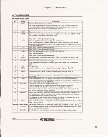
PIN FUNCTIONS · l297
N ' NAME FUNCTION
1 SYNC Outp ut of the on-chip choppe roscillalor.
The SYNC comections The SYNC ronnections of all L297s to be synchronized are
connected together and the oscillator components are onitted on all but one. If an
external clock source is used it is irlected at this terminal .
2 GND Ground connection.
3 HOME Open collector outp ut thai indicat es when the L297 is in its initial state (ABCD _ 0101).
The transistor is open when this signal is active .
• A Motor erase A drive sinnal for DOWer stece.
S INH 1 Active IoN inhibit control lor driver stage of A and B phases.
When a bipolar bridge is used this signal can be used to ensure fast decay 01load
curr ent when a winding is de-energized . Also used by chopper to regulate load curren t if
CONTROL input is low.
S B Motor phase B drive signal for power staoe.
7 C Motor cha se C drive siana! for DOWer staae.
8 INH2 Activ e low inhibit control lor drive stages of C and O phases.
,. 0 Motor phase 0 drive signal tor power stage.
same functions as INH1.
9
ENABLE Chip enable input. When low Qnactive) INH1, INH2, A, B, C and D are brought low.
11 CONTROL Control input that defines action of chopper,
When low chopper acts on INH1 and INH2; when high chopper acts on phase lines
ABCD.
12 V. SV supply input.
13 SENS2 Input for load current sense voltage from power stages of phases C and D.
,. SENSI Input for load current sense voltage from power slages of pha ses A and B.
is Vret Reference voltage for chopper circuit. A voltage applied to this pin determin es the peak
load current.
18 OSC An AC network (A 10 Vee, C to ground) connected to this terminal oeterrranes the
chopp er rate. This tenn inal is connected to ground on all but one device in synchronized
multi - L297 configurations. f '" 1/0.69 AC
17 CW/CCW Clockwise/counterclockwise direction control input.
Physical direction of motor rotation also depends on connection 01windings
Svnchronized internallv therefore direction can be chanaed at anv time.
18 CLOCK Slep clock. An active low pulse on this input advances the motor one increment. Th,
step occurs on the rising edge of this signal.
19 HALF/FULL Halll1ull step select input. When high selects hall slep operation, when low selects full
step operation. One-phase-on lull step mode is obtained by selecting FUll when the
l29Ts translator is at an even-num bered slate.
Two-phase-on full step mode is set by selecting FULL when the translator is at an odd
numbered position. (The home oosition is desianate state 1t
2. RESET Reset input. An active low pulse on this input restores the translalor to the home position
L slale " ABeD - 0101t
PIN FUNCTIONS - L297 A Pin function of the l297A are identical to those of the,L297 exceot lor pins 1 and 11)
1 DOUBLER An RC network conne cted to this pin dete rmines the delay between an input clock pulse
and the corr espondina ohost Dulse .
11 DIR-MEM Direction Memory. Inverted output 01the direction flip flop. Open collector output.
16/ 18
61