
Page 66 - CNC Robotics
P. 66
I -- -----'------'----
Chapter 2 / Electronics
I APPLICATION NOTE
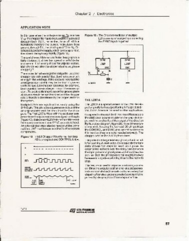
Inthis case when the voltage seeress As reaches Figure 19: The Chopperosci1lator of multiple
VREF thechopperflipflopis resetand INH1activated L297sare synchronizedby connecting
(brought low). lNH 1, remember, turns off all four the SYNC Inputs together.
transistors therefore the current recirculates from
ground, through 02 , the winding and 03 to Vs. Di-
schargedacrossthesupply,whichcanbe upto 46V, ----
the current decays very rapidly (figure 18). I,
The usefulnessof thissecondfasterdecayoptionis I
fairly obvious; it allows fast operation with bipolar SYNC SYNC
motors and it is the only cho ice for unipolar rro tors. L297 L297
But why do we offer the slower alternative, phase osc osc
chopping? '. 16
sv I" R 11&
Theanswer isthatwe might beobligedto use a low
chopper rate with a motor that does not store much
energy in the windings. If the decay is veryfast the ' ±c
average motor current may be too low to give an s_se·Ufl --
usefultorque. Lowchopper ratesmay, for example,
be irrposed ifthere is a larger rrotor inthe samesy·
stem.To avoidswitching noise onthe groundplane
alldrivers should be synchronizedand the chopper
rate is therefore determined by the largest motor in
the system. THE L297A
c. Multiple L297s are synchronized easily using the The L297Ais a special version of the L297 develo-
SYNC pin. This pin is the squarewave output of the ped originally for head positioning in floppy diskdri-
on-chip oscillatorand the clock input for the chop- ves. It can, however,be used in other applications.
pers.The first L297 is fitted with the oscillator com- Compared to the standard L297 the difference are
ponentsa ndoutputs a sqarewavesignal on this pin
the addition of a pulse doubleron the step clock in·
(figure19). SubsequentL297sdo not needtheoscil- put and the availability of the output of the direction
lator componentsand use SYNC as a clock input. flipflop (blockdiagram,figure 20). Toadd these fun-
An external clock may alsobe injected at this termi- ctions while keeping the low-cost 20·pin package
nal if an L297 mustbesynchronized to othersystem the CONTROLand SYNC pins are not availableon
components. this version (they are note needed anyway). The
Figure 18: Inhibit Chopper Waveforms. Winding chopper acts onthe ABCD phase lines.
AB is energizedand CONTROL is low. The pulsedoublergeneratesa ghostpulseinternal-
Iy for each input clockpulse.Consequentlythetran-
slator moves two steps for each input pulse. An
external AC network sets the delay time between
the input pulseand ghost pulseand should be cho-
• sen so that the ghost pulses fall roughly halfway
between inputpulses,allowing time for the rrotor to
step.
This feature is used to improve positioningaccura-
cy. Sincethe angularpositionerror of ast eppermo-
toris noncumulative(itcancelsout to zeroeveryfour
stepsin afour stepsequencemotor) accuracy is im-
provedby stepping two of four steps at a time.
I
12/18
l.
57
I
I
~-----------------~