
Page 62 - CNC Robotics
P. 62
Chapter 2 / Electronics
APPLICATION NOTE
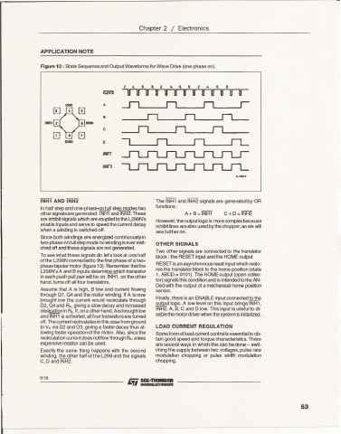
Figure 12 : State Sequence and Output Waveforms for Walle Drive (one phase on).
4 • • 4 , • 2 4 , •
ffiX'i<
""'" 4 JI n n r
•
c -,
- n n !L
D
INH2
!>_!>KJ
INHI AND INH2 The INHl and INH2 signals are generated by OR
In ha lf step and one-phase<ln full step modes two functions:
othersignals aregeneraled: INHI ancIINH2.These A+ B = INHl C + D =INH2
are inhibit signals which arecoupled to the 1298N's However,the outputlogicis morecomplexbecause
enable inputs and serveto speedthe current decay inhibit lines arealso usedby the chopper,as we will
when a winding is switched off.
see further on.
Since both windings are energizedcontinuouslyin
two-phase-onfull step mode no winding iseverswit- OTHER SIGNALS
ched off and these signals are not generated.
TIM) other signals are connected to the translator
To see what these signals do let's look at one half block : the RESET input and the HOME output
of the L298Nconnectedto thefirsl phase of a two-
RESETis an asynchronousreset input which resto-
phase bipolar motor (figure 13). Remember that the
L298N's A and B nputs determine which transistor res the translator block to the home position (state
in each push pull pair will be on. INH1, on the other 1, ABCD= 0101).The HOMEoutput (open collec-
hand, turns off all four transistors. tor) signalsthis conditionand is intended to the AN-
Ded wlh the output of a mechanicalrome position
Assume that A is high, B low and current flowing sensor.
through 01, 04 and the motor winding. If A isnow
brought low the current would recirculate through Fnally, there is an ENABLE iflJut connected to the
02,04 and Rs.giving a slow decay and increased output logic. A low level on this input brings INH1,
INI-l2, A, B, C and D low. This input is useful to di-
, dissipationin Rs.If,onaotherhand, Aisbrought b w sablethe rrotordriver when the systemisinitialized.
and INH1 is activated,all fourtransistorsare turned
L off.Thecurrentrecirculates inthiscase fromground LOAD CURRENT REGULATION
to Vs via D2 and 0 3, giving a fasterdecay thus al-
lowing faster operationof the motor. Also, since the Some form of load current controlis essentialto ob-
recirculationcurrent does notflowthrough As, aless tain good speed and torque characteristics.There
expensiveresistor can be used. are several ways in which this can be done - swit-
Exactly the same thing happens with the second ching the supply betweentwo voltages, pulse rate
winding, the other half of the L298 and the signals modulation chopping or pulse width modulation
C, D and INH2. chopping.
8/18
53